Ptrotek | Industrial Services | Inspection Services

We have long experience in oil & gas industry ...

For more info, Contact Us

Our Articles

You can choos our articles from menu in below …

Ferrous and non-ferrous materials are the two broad categories of metals, based on presence and absence of iron as a principle ingredient respectively. Non-ferrous materials can be defined as the material that does not contain iron in an appreciable amount.

Nonferrous metals found their application in the wide variety of industrial and commercial application such as copper in electrical devices, aluminum in structural applications, zirconium as a refractory material, etc. 

Like ferrous materials, non-ferrous materials also make alloys with other metals. For instance, brass and bronze are the typical alloys of copper. 

Non-ferrous Materials – Copper and its Alloys

Copper finds its application in electrical devices and heat exchangers due to high electrical (5.96×10⁷ S/m) and thermal conductivity (385 W/m.K). Pure copper in nonmagnetic is having the tensile strength of 220-413 MPa (32000, 60,000 psi).

Pure copper is not suitable for welding; it ‘s hard to machine due to its ductility. Copper is used in heat exchangers and boilers due to high heat conductivity. Specifications for seamless copper pipes and tubes standard sizes are given in ASME II part-B SB-42 and SB-75. 

There are more than 400 copper alloys each with the unique combination of properties. The tensile strength of copper alloys is greater than pure copper (50,000-90,000 psi/ 344-620 Mpa). Some of the copper alloys are listed below:

  • Brass:                   Alloy of copper (50-95%) and zinc (5-50%)
  • Bronze:                 Alloy of Copper (88%) and Tin (12%)
  • Copper-Nickel        Alloy of copper (66-90%) and Nickel (10-30%)
  • Beryllium-copper    Alloy of copper (97-99.5%) and Beryllium (0.5-3%)

Non-ferrous Materials – Aluminum and its Alloys
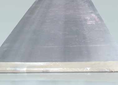
The aluminum is the a non-ferrous material. The light weight of aluminum metal finds its use in oil and gas storage containers and drill pipes, aircraft structures, railway cars, etc. Aluminum has a high tendency for casting, forging, machining, and welding.

The tensile strength of pure aluminum is 41-110 MPa (6000-16000 psi). Specifications for aluminum and aluminum alloy sheets, plates, drawn seamless tubes, bars, rods are given in ASME II part-B.

The Aluminum Association has designated the four digits system for identifying the aluminum alloys. The list of groups of aluminum alloys is given below

Alloy Group    Alloying element

  • 1 xxx    Pure aluminum ( purity 99.0 % or greater)
  • 2 xxx    Copper
  • 3 xxx    Manganese
  • 4 xxx    Silicon
  • 5 xxx    Magnesium
  • 6 xxx    Magnesium & Silicon
  • 7 xxx    Zinc
  • 8 xxx    Other elements

The first digit represents the alloying element while the last “xx” represents the minimum amount of aluminum in the alloy.

For instance, the minimum aluminum content of 1350 is 99.50%. The second digit in the group indicates the minor modification of the basic alloy. 

Non-ferrous Materials – Nickel and Alloys

The high resistance of nickel to corrosion finds its applications in oil and gas production and marine engineering. Both ferrous and nonferrous alloys made up of nickel shows excellent corrosion resistance to chemicals and sour oil and gas environments.

Pure nickel has a tensile strength of 317 Mpa (46000 psi). The nickel alloys have low thermal expansion and low electrical conductivity. Some major types of nickel alloys are iron-nickel-chromium alloy, copper-nickel alloy, nickel-chromium alloy, etc.

The specifications for nickel and nickel alloy plates, sheets, strips bars, rods, pipes, tubes and wires are given in ASME II part-B.  Stainless steel contains nickel as an alloying metal typically 8-10%.

Monel metal is another highly corrosion resistance alloy of nickel with 67% nickel, 29% copper, and small percentages of iron and manganese.

The high nickel content resists the chloride ion stress corrosion cracking. Chromium content confers resistance to corrosion in oxidizing conditions and sulfur compounds. 

Cobalt and its Alloys

Cobalt is temperature resistant with the melting point of 1493 °C (2720 °F). It is used as an alloying element in high-speed tool bits and cutters, creep resistant, high-temperature alloys. Pure cobalt has a tensile strength of 234 Mpa (34000 psi). However, it is seldom used in its pure form.

The tensile strength of cobalt alloy (stellite 21) is high (696 Mpa / 101,000 psi). Cobalt can be machined, cold-drawn and welded. ASME II part-B SB-818 provides the specification for cobalt-chromium-nickel-molybdenum-tungsten alloy plate, sheet and strip. 

Return to Industrial Inspection

Executive Summary & Industrial Inspection Scope

In demanding industrial environments across Oil, Gas, Petrochemical, Offshore, and Heavy Process Infrastructure, rigorous compliance with ASME Section IX, AWS D1.1, EN ISO 15614 is essential to ensure operational integrity, personnel safety, and compliance with statutory regulatory frameworks. This technical specification provides QA/QC managers, procurement engineers, welding inspectors, and third-party inspection (TPI) agencies with an authoritative, field-tested guideline for “What Is The Non Ferrous Materials”.

Ensuring compliance regarding what is the non ferrous materials minimizes the risk of catastrophic asset failures, costly unscheduled shutdowns, and supplier non-conformances. The following technical sections delineate the scope of inspection, mandatory verification protocols, acceptance criteria, documentation deliverables, and root cause mitigation strategies.

Governing International Engineering Codes & Specifications

Verification and validation of What Is The Non Ferrous Materials must strictly conform to the latest editions of the following international engineering codes and project specifications:
• **Primary Standard Reference:** ASME Section IX, AWS D1.1, EN ISO 15614
• **Quality Management & Inspection Systems:** ISO 9001:2015 & ISO/IEC 17020 (Requirements for the operation of various types of bodies performing inspection)
• **Material Compliance & Traceability:** EN 10204 Type 3.1 / 3.2 Inspection Certificates for metallic and non-metallic pressure-retaining components
• **Personnel Qualification:** ASNT SNT-TC-1A / ISO 9712 for NDT personnel, CSWIP 3.1 / AWS CWI for welding inspection, and NACE / AMPP Level 2/3 for coating and corrosion personnel
• **Statutory & Health Safety Directives:** ASME Boiler & Pressure Vessel Code (BPVC), API Standards, OSHA, and regional local authority regulations.

Step-by-Step Quality Control & Inspection Procedure

The execution of quality surveillance for What Is The Non Ferrous Materials is structured across four progressive QA/QC intervention phases:

Stage 1: Pre-Inspection & Engineering Document Review (Review Point – R)

Prior to commencement of any physical activities or manufacturing operations related to What Is The Non Ferrous Materials, the contractor or vendor must submit all technical submittals to the Owner or TPI agency for formal review and approval.

  • Verification of approved Inspection and Test Plan (ITP) identifying all Hold (H), Witness (W), Review (R), and Surveillance (S) intervention points.
  • Cross-examination of Material Test Reports (MTR / Mill Certificates) against standard design specifications (ASME Section IX, AWS D1.1, EN ISO 15614).
  • Review and approval of specific Procedure Qualification Records (PQR), Welding Procedure Specifications (WPS), or calibration certificates.
  • Verification that all measurement instruments, gauges, and NDT equipment hold valid calibration certificates from ISO/IEC 17025 accredited calibration laboratories (within 6 to 12 months validity).

Stage 2: In-Process Witnessing & Fabrication Control (Witness / Hold Point – W/H)

During the active execution phase, the certified inspector performs physical surveillance to ensure strict adherence to certified drawings, manufacturing procedures, and code tolerances.

  • Verification of material traceability (heat number, heat treatment lot, plate number) transferred accurately onto fabricated components.
  • Dimensional verification and visual inspection using calibrated gauges, micrometer depth dials, or laser alignment systems.
  • Monitoring ambient environmental parameters (relative humidity, dew point, substrate temperature) when applying surface treatments, welding preheat, or pressure testing.
  • Witnessing non-destructive examination (RT, UT, MT, PT, PMI) at specified percentages according to project critical rating and code requirements.

Stage 3: Final Acceptance, Pressure/Performance Testing & Marking (Hold Point – H)

The culminating milestone where the fully assembled or completed item is subjected to definitive acceptance tests in the presence of the Owner’s Third-Party Inspector (TPI).

  • Execution of pressure proof tests (Hydrostatic at 1.3x to 1.5x MAWP or Pneumatic test) with dual calibrated pressure gauges and temperature recorders.
  • Full visual inspection of completed surfaces, welds, protective coatings, and flange contact faces for absence of mechanical damage or code defects.
  • Validation of permanent stamping, low-stress die markings, nameplate data verification, and barcoding in strict conformity with project specs.
  • Clearing all open punch-list items, non-conformance reports (NCRs), and concession requests prior to issuance of the release note.

Stage 4: Packing, Preservation & Inspection Release (Inspection Release Certificate – IRC)

Ensuring the inspected equipment is adequately protected against atmospheric corrosion, mechanical shock, and marine transit degradation.

  • Inspection of rust preventative coatings, desiccant bags, flange face blind protectors, and vapor corrosion inhibitor (VCI) packaging.
  • Verification of heavy-lift sea fastening lugs, center-of-gravity markings, and export crating compliance (ISPM 15 wooden crating).
  • Compilation and signing of the final Inspection Release Certificate (IRC / Shipping Release) and manufacturer data dossier (MDR).

Technical Acceptance Criteria & Tolerances Matrix

All measurements and physical characteristics must comply with the engineering tolerances and acceptance thresholds tabulated below:

Welding Variable / Test Item Governing Code (ASME Sec IX / AWS) Permissible Tolerance / Requirement Test Method / Verification QC Intervention
P-Number & Group Number Verification ASME Sec IX QW-420 Base metal must strictly match qualified P-Number/Group Number on PQR MTR Chemical Analysis & Positive Material Identification (PMI) Review (R)
F-Number & A-Number Filler Metal Control ASME Sec IX QW-430 & QW-440 Filler rod/wire must match certified AWS classification with heat/lot batch certs Batch Test Certificate & Oven Storage Temperature Check (>120°C) Witness (W)
WPS Essential Variables Tolerances ASME Sec IX QW-250 to QW-265 Current/Voltage ±10%, Travel speed ±10%, Heat input within qualified maximum J/mm Calibrated Digital Clamp Meter & Heat Input Calculation Surveillance (S)
Preheat & Interpass Temperature ASME Sec IX / ASME B31.3 Preheat maintained at min specified temp 75mm on each side; max interpass not exceeded Tempilstik (Temperature crayon) / Calibrated Contact Pyrometer Witness (W)
Post-Weld Heat Treatment (PWHT) ASME Sec VIII Div 1 UCS-56 Heating rate, soaking time (1 hr per 25mm), and cooling rate within strict code graph Thermocouple placement & Multi-channel Temperature Recorder Chart Hold (H)
Tensile & Guided Bend Mechanical Tests ASME Sec IX QW-150 / QW-160 Tensile strength not lower than base metal min specified; bend specimens: zero open flaw >3.2mm Destructive Lab Testing (Accredited ISO 17025 Lab) Hold (H)

Mandatory QA/QC Dossier & Inspection Deliverables

Prior to the final issuance of the Inspection Release Certificate (IRC), the contractor and vendor must compile and submit the verified manufacturer data record containing:

  • Approved Inspection & Test Plan (ITP) with sign-off stamps by Contractor, Client, and TPI.
  • Material Test Reports (MTR / Mill Test Certificates EN 10204 Type 3.1 or 3.2).
  • Certified Welding Procedure Specifications (WPS), Procedure Qualification Records (PQR), and Welder Performance Qualifications (WPQ).
  • Calibration Certificates for all test instruments and measuring equipment (NABL / ISO 17025 accredited).
  • Non-Destructive Examination Reports (RT, UT, MT, PT, PMI, Ferrite Content) evaluated by Level II/III inspectors.
  • Heat Treatment & PWHT Time-Temperature Recorder Charts with thermocouple layout drawings.
  • Hydrostatic / Pneumatic Pressure Proof Test Certificate with calibrated chart recorder logs.
  • Surface Preparation and Protective Coating Inspection Reports (Daily environmental log, blast profile, DFT summary).
  • Non-Conformance Report (NCR) and Concession Disposition Closeout Log.
  • Official Inspection Release Certificate (IRC / Shipping Release Note) permitting packing and dispatch.

Common Non-Conformances & Field Mitigation Strategies

Based on extensive third-party inspection field records in oil & gas projects, the following deviations require heightened surveillance:

Defect / Hazard: Material Grade Substitution & Lack of Heat Traceability

Root Cause: Uncontrolled workshop storage, missing color coding, or unverified supplier sub-tier procurement without EN 10204 3.1 documentation.

Preventative Action: Enforce strict 100% Positive Material Identification (PMI) prior to cutting, and mandatory material receiving inspection with physical stamping cross-referenced to original mill test certificates.

Defect / Hazard: Out-of-Tolerance Fit-Up & Alignment Mismatch

Root Cause: Poor thermal cutting, thermal distortion from excessive preheat, or inadequate jigging and tacking arrangements.

Preventative Action: Establish a mandatory Witness/Hold point at joint fit-up before root pass deposition. Use calibrated Hi-Lo gauges to verify bevel angle, root face, and root gap according to the qualified WPS.

Defect / Hazard: Premature Coating Delamination & Blistering Under Film

Root Cause: Excessive soluble salt contamination (>20 mg/m²) left on the substrate, blast cleaning below dew point (<3°C above dew point), or oil/moisture in the blasting compressor air line.

Preventative Action: Perform Blotter Test (ASTM D4285) daily on compressed air, enforce Bresle patch chloride testing, and apply primer within 4 hours of abrasive blasting before rust blooming initiates.

Defect / Hazard: Pressure Drop During Final Hydrostatic Proof Testing

Root Cause: Micro-leakage through temporary test flange gaskets, entrapped air pockets inside vessel high points, or inadequate temperature stabilization.

Preventative Action: Ensure thorough venting at all high-point vents until bubble-free fluid emerges, allow minimum 15-minute temperature stabilization between filling medium and ambient metal, and torque all blind flanges with calibrated torque wrenches.

Frequently Asked Questions (FAQ)

Q: What are the mandatory qualifications for inspectors verifying What Is The Non Ferrous Materials?

A: Inspectors must hold recognized international certifications applicable to the discipline. For welding and fabrication: CSWIP 3.1/3.2, AWS CWI, or API 510/570 Source Inspector. For NDT: ISO 9712 or ASNT SNT-TC-1A Level II minimum. For coatings: NACE / AMPP Level 2 or FROSIO Level III. Additionally, the inspection agency must operate under an ISO/IEC 17020 accredited quality management system.

Q: How does PtroTek resolve non-conformances (NCRs) encountered during vendor surveillance?

A: When a deviation from certified drawings or ASME Section IX, AWS D1.1, EN ISO 15614 is detected, the inspector issues a formal Non-Conformance Report (NCR) within 24 hours. The vendor must submit a Root Cause Analysis (RCA) and proposed disposition (Rework, Repair, or Concession). Work on the affected component is halted (Hold Point) until the Owner’s engineering authority approves the disposition and a re-inspection confirms full compliance.

Q: What is the difference between Witness (W) and Hold (H) points in an Inspection & Test Plan (ITP)?

A: A Hold Point (H) is a mandatory milestone where fabrication or testing CANNOT proceed without the physical presence of the designated client or third-party inspector. Written clearance or stamping is strictly required. A Witness Point (W) requires prior notification (typically 24 to 48 hours) to the inspector; however, if the inspector fails to attend at the scheduled time, fabrication or testing may proceed with subsequent review of the test records.

Q: Can international clients review inspection reports and photos in real time?

A: Yes. PtroTek provides comprehensive Flash Reports issued within 24 hours of inspection completion, followed by detailed formal inspection reports accompanied by high-resolution calibrated photographic evidence, dimension logs, and signed vendor test records for complete global transparency.

Need Certified Third-Party Inspection (TPI) Support?

PtroTek provides international vendor surveillance, ASME code vessel inspection, welding QA/QC, and protective coating verification across Southeast Asia, the Middle East, and global fabrication hubs.

Request a Technical Inspection Quote