Ptrotek | Industrial Services | Inspection Services

We have long experience in oil & gas industry ...

For more info, Contact Us

Our Articles

You can choos our articles from menu in below …

The Pressure Vessel Dimension Inspection article provides you with information about the dimensional requirements in pressure vessel construction and pressure vessel inspection.

You may know some fabrication tolerances have not been addressed in ASME Code Section VIII.

So you need to refer to other sources for inspection. This article provides you the most important dimensional inspection requirements.

The dimensional check of a pressure vessel consists of the following items:

  • Mill Undertolerance of Plates and Pipes
  • Tolerances for Formed Heads
  • Out of Roundness of shell
  • Nozzles and attachments Orientation
  • Nozzles and attachments Projection
  • Nozzles and attachments elevation
  • Nozzles and attachments levelness
  • Weld mismatch
  • Weld reinforcement

Mill Undertolerance of Plates and Pipes

Pressure Vessel Dimension Inspection – Plate:

Your pressure vessel plates with 0.01 inch or 6% undertolerance, whichever is smaller, may be used for full design pressure, instead of at the given design thickness specified.

However, if the material specification allows greater undertolerance, then the ordered thickness for the material should be sufficiently greater.

For example, if you have SA 516 Gr.70 plate with a 0.625 inch nominal thickness, and the actual thickness is 0.615, it is acceptable, and you may use this plate without any specific design consideration.

But if the same plate has an actual thickness of 0.595 inches, you need to consider mill undertolarence in your design calculation.

This plate thickness is acceptable based on the material specification (see table in SA 20 for thickness tolerances). We cannot reject this plate because it is in the permissible tolerance of plate specification, but based on ASME Code SEC VIII Div 1, you need to consider this 0.03 inches in your design calculation: e.g. Thickness = Min Thickness + Corrosion Allowance + Mill Undertolrance

Pressure Vessel Dimension Inspection – Pipe:

Contrary to the plate material, your pipe and tube mill undertolrances need to be taken into account for design consideration.

Pipe and tube undertolrances are almost -12.5 % of the nominal wall thickness, but sometimes there are differences for different materials, so for any specific material, it shall be referred to the suggested pipe or tube material specification to obtain the exact amount of mill undertolrances.

For example, if there is a pressure vessel with nominal shell thickness of 0.5 inch, it needs a 6” SA 106 Gr.B nozzle to be attached to the shell plate.

Assume that external loading is not a design controlling factor (is not governor), so as our minimum, nozzle thickness will be the same as the shell thickness.

So with a consideration of -12.5%, the calculation will be: 0.5 / 0.875 = 0.571 inches. So when we refer to ASME B36.10 and select our pipe schedule it will be SA 106 Gr.B Schedule 160.

Pressure Vessel Dimension Inspection – Tolerances for Formed Head:

You may know that there is a specific rule for dimensional checking of formed heads, based the fact that the UG-81 inner surface shall not deviate outside of the specified shape more than 11⁄4% of D and inside the shape more than 5⁄8%.

You can use sweep boards, which are made by cutting a thin steel sheet or piece of wood for checking your crown and knuckle radius.

For your skirt, the difference between the maximum and minimum inside diameter, should not be more than 1%, and you can use a tape measure or laser measure for dimensional control of the skirt.

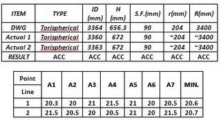
So to fully understand, let’s check the following head together:

Head ID = 3364 mm

Head Type: Torispherical

Limit for Outside of specified Shape = 3364 x 1 ¼% = 42.05 mm

Limit for Inside of specified Shape = 3364 x 5/8 % = 21.025 mm

So we check the depth, and the drawing is 656.3 mm and the actual is 672 mm, so it is outside of the shape. We need to check if it is in the range of tolerance, so the maximum outside of the shape will be 42.05 + 656.3 = 698.35 so our actual value is 672 mm. 672<698.35, so it is OK.

We cut a sweep board equal to the head drawing crown radius (3400 mm) and other one for the knuckle radius equal to 204 mm, so we try to fit the sweep boards in the heads for the above example of the sweep boards. The edge distance to the head surface should not be deviate from the above limited values.

Skirt max and min ID should not be more than 1% of the ID, which is 33.64 mm. So, in the above example skirt is also is OK. Our nominal thickness is 20 mm, so up to 19.746 is acceptable then for the above example. The thickness dimension is also OK.

So the above head dimensions are ok

Pressure Vessel Dimension Inspection – Out of Roundness of Shell:

UG-80 deals with out of roundness of shell. The maximum permitted ovality tolerance (D max – D min) shall not exceed 1% of the nominal diameter of the vessel.

If you have an opening, then the tolerance can be increased by 2% x d (d = diameter of opening), if the measurement is taken within a distance of ‘d’ from the axis of the opening.

The out of roundness generally is measured in two directions with a normal measuring tape or laser measure, so one direction would be the D max and other one would be the D min.

The following picture shows an out of roundness measurement:

Pressure Vessel Dimension Inspection – Nozzles and Attachments Orientation:

ASME Code SEC VIII Div 1 has not specified the orientation tolerances for nozzles and attachments, so you need refer to the pressure vessel handbook.

It is almost +/- 1 degree. The orientation check can be done by a simple calculation by using a measuring tape in the actual measurement work on the vessel.

For example, we want to check N3 orientation in following drawing.

N3 is located at 120 degrees in the drawing. The manufacturer has located this point in the vessel with a marker, and we want to check the location, and if it is OK, then we can allow the manufacturer to cut.

So we run this simple calculation:

Vessel OD = 97.875”

Shell outside Circumference length = π x OD = 3.14 x 97.875 = 307.3275”

307.3275 distributed to 360 degrees so each degree represents

307.3275/ 360 =0.8536”

N3 is located at the 120 degree position, so if we use a measuring tape and keep 0 at the zero reference point in the vessel and pull the tape, the nozzle center should be located at 120 x 0.8536 = 102.4425 inches.

This 102.4425 is a perfect case so our tolerance is ±1 degrees. So if the tape shows in following range, it will be OK.

102.4425 – 0.8536 =101.5889”

102.4425 + 0.8536 =103.2961”

Pressure Vessel Dimension Inspection – Nozzles and Attachments Projection:

Nozzle and attachment projection is the length from the nozzle or the attachment face to the vessel shell centerline.

Projection dimensions are addressed in general assembly drawings. The projection tolerances are not addressed in ASME Code SEC VIII Div 1, but if you refer to the pressure vessel handbook, almost ± 0.25 of an inch is permissible.

In following figure, we need to check the BD nozzle projection. It should be 660 mm in distance from shell centerline to the flange face.
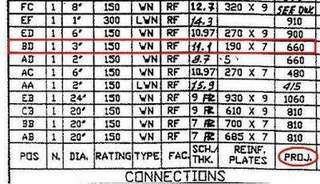
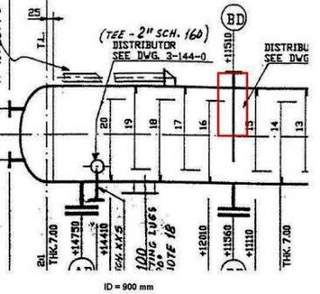
In practical measurement, you may use a measuring tape to measure the distance between the shell outside circumference to the nozzle face. Then the measured value is summed with the shell thickness and the inside radius. So for the above example, the following range is acceptable:
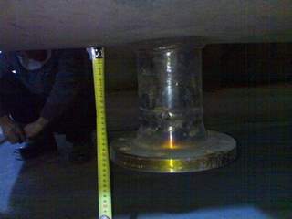
660 – 6.35 = 653.65

660 + 6.35 =666.35

Pressure Vessel Dimension Inspection – Nozzles and Attachments Elevation:

Your Nozzles and attachments elevation is the length between the nozzles or the attachments centerline and the bottom or top head tangent line.

The elevation dimension is addressed directly in the general assembly drawing. The elevation tolerances are not addressed in ASME Code SEC VIII Div 1, but if you refer to the pressure vessel handbook, almost ±0.25 inch is permissible.

In following figure, we need to check Nozzle EB elevation. As you see in the drawing, the distance between the nozzle centerline to the bottom head tangent line is 700 mm.
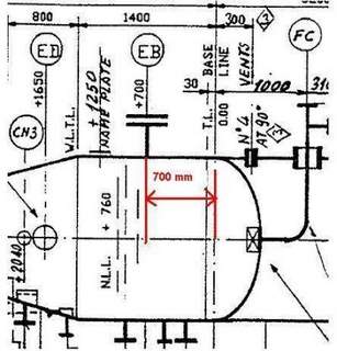
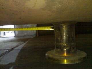
In actual measurement, the measuring tape or laser measure is used to measure from the nozzle neck center line to the tangent line. In this example, the following range is acceptable:

700 – 6.35 = 693.65

700 + 6.35 = 706.35

Pressure Vessel Dimension Inspection – Nozzles and Attachments Levelness:

The nozzles and attachments levelness tolerances are not addressed in ASME Code SEC VIII Div 1, but in the pressure vessel handbook, a ½ ˚ deflection is permissible.

For levelness checking, a level gage is used. If the bubble is in the middle of the designated lines, the nozzle is level.

But if the bubble intersects the designated limit lines, you need to run a simple calculation and see if your deflection is within the tolerance limit.
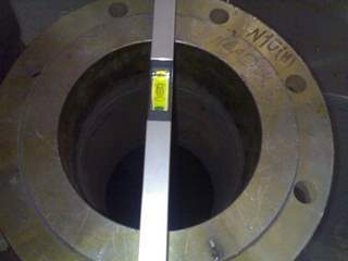
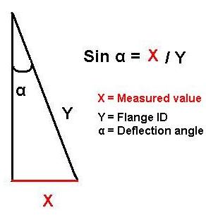
You need to move one end of the level gage up to the bubble to be placed in middle. Then measure the distance between the level gage end and the flange face. The measured value is the X in the figure.

Then obtain α, if α is less than 0.5˚, the deflection falls within the tolerances. And it is OK otherwise it will require cutting out and re-welding.

Pressure Vessel Dimension Inspection – Weld Mismatch:

ASME Code SEC VIII Div. 1 specified tolerances for weld mismatch in UW-33. It is important to know that the limit for weld mismatch is stringent for a category A weld (Longitudinal joint and circumferential shell to hemispherical head).

The concept behind this is that the longitudinal joint bears double the amount of stress, and inspectors should precisely check these joints.

For example, you have a pressure vessel with a nominal thickness of 1 inch. You do a visual and measure the mismatch by the welding gauge. Assume you found a 0.143 inch mismatch in one longitudinal and one circumferential joint.

So you look to the UW-33 table:
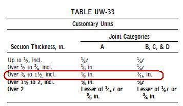
The permissible weld mismatch in the longitudinal joint for your case is 0.125 of an inch, and for the circumferential joint, it is 0.1875 of an inch.

Your weld mismatches for both longitudinal and circumferential joints are 0.143, so your circumferential joint is OK, but your longitudinal joint should be repaired.

Pressure Vessel Dimension Inspection – Weld Reinforcement:

The same concept for weld mismatch exists for weld reinforcement tolerances. The longitudinal joint weld reinforcement limit is more stringent than that for circumferential joints.

This is because longitudinal joint bears double stress, and it is required that the stress concentration is minimized.
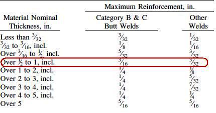
In the same example, assume that there are 0.150 of an inch welds reinforcement for both category A and B welds. Do you want to review your weld acceptance?

Category A allowances = 0.093 inch

Category B allowances = 0.1875

So our circumferential joint is OK, but the longitudinal is not OK and should be repaired by removing the excess weld reinforcement.

Executive Summary & Industrial Inspection Scope

In demanding industrial environments across Oil, Gas, Petrochemical, Offshore, and Heavy Process Infrastructure, rigorous compliance with ASME BPVC Section VIII Div 1 & 2, Section IX, Section V is essential to ensure operational integrity, personnel safety, and compliance with statutory regulatory frameworks. This technical specification provides QA/QC managers, procurement engineers, welding inspectors, and third-party inspection (TPI) agencies with an authoritative, field-tested guideline for “Pressure Vessel Dimension Inspection”.

Ensuring compliance regarding pressure vessel dimension inspection minimizes the risk of catastrophic asset failures, costly unscheduled shutdowns, and supplier non-conformances. The following technical sections delineate the scope of inspection, mandatory verification protocols, acceptance criteria, documentation deliverables, and root cause mitigation strategies.

Governing International Engineering Codes & Specifications

Verification and validation of Pressure Vessel Dimension Inspection must strictly conform to the latest editions of the following international engineering codes and project specifications:
• **Primary Standard Reference:** ASME BPVC Section VIII Div 1 & 2, Section IX, Section V
• **Quality Management & Inspection Systems:** ISO 9001:2015 & ISO/IEC 17020 (Requirements for the operation of various types of bodies performing inspection)
• **Material Compliance & Traceability:** EN 10204 Type 3.1 / 3.2 Inspection Certificates for metallic and non-metallic pressure-retaining components
• **Personnel Qualification:** ASNT SNT-TC-1A / ISO 9712 for NDT personnel, CSWIP 3.1 / AWS CWI for welding inspection, and NACE / AMPP Level 2/3 for coating and corrosion personnel
• **Statutory & Health Safety Directives:** ASME Boiler & Pressure Vessel Code (BPVC), API Standards, OSHA, and regional local authority regulations.

Step-by-Step Quality Control & Inspection Procedure

The execution of quality surveillance for Pressure Vessel Dimension Inspection is structured across four progressive QA/QC intervention phases:

Stage 1: Pre-Inspection & Engineering Document Review (Review Point – R)

Prior to commencement of any physical activities or manufacturing operations related to Pressure Vessel Dimension Inspection, the contractor or vendor must submit all technical submittals to the Owner or TPI agency for formal review and approval.

  • Verification of approved Inspection and Test Plan (ITP) identifying all Hold (H), Witness (W), Review (R), and Surveillance (S) intervention points.
  • Cross-examination of Material Test Reports (MTR / Mill Certificates) against standard design specifications (ASME BPVC Section VIII Div 1 & 2, Section IX, Section V).
  • Review and approval of specific Procedure Qualification Records (PQR), Welding Procedure Specifications (WPS), or calibration certificates.
  • Verification that all measurement instruments, gauges, and NDT equipment hold valid calibration certificates from ISO/IEC 17025 accredited calibration laboratories (within 6 to 12 months validity).

Stage 2: In-Process Witnessing & Fabrication Control (Witness / Hold Point – W/H)

During the active execution phase, the certified inspector performs physical surveillance to ensure strict adherence to certified drawings, manufacturing procedures, and code tolerances.

  • Verification of material traceability (heat number, heat treatment lot, plate number) transferred accurately onto fabricated components.
  • Dimensional verification and visual inspection using calibrated gauges, micrometer depth dials, or laser alignment systems.
  • Monitoring ambient environmental parameters (relative humidity, dew point, substrate temperature) when applying surface treatments, welding preheat, or pressure testing.
  • Witnessing non-destructive examination (RT, UT, MT, PT, PMI) at specified percentages according to project critical rating and code requirements.

Stage 3: Final Acceptance, Pressure/Performance Testing & Marking (Hold Point – H)

The culminating milestone where the fully assembled or completed item is subjected to definitive acceptance tests in the presence of the Owner’s Third-Party Inspector (TPI).

  • Execution of pressure proof tests (Hydrostatic at 1.3x to 1.5x MAWP or Pneumatic test) with dual calibrated pressure gauges and temperature recorders.
  • Full visual inspection of completed surfaces, welds, protective coatings, and flange contact faces for absence of mechanical damage or code defects.
  • Validation of permanent stamping, low-stress die markings, nameplate data verification, and barcoding in strict conformity with project specs.
  • Clearing all open punch-list items, non-conformance reports (NCRs), and concession requests prior to issuance of the release note.

Stage 4: Packing, Preservation & Inspection Release (Inspection Release Certificate – IRC)

Ensuring the inspected equipment is adequately protected against atmospheric corrosion, mechanical shock, and marine transit degradation.

  • Inspection of rust preventative coatings, desiccant bags, flange face blind protectors, and vapor corrosion inhibitor (VCI) packaging.
  • Verification of heavy-lift sea fastening lugs, center-of-gravity markings, and export crating compliance (ISPM 15 wooden crating).
  • Compilation and signing of the final Inspection Release Certificate (IRC / Shipping Release) and manufacturer data dossier (MDR).

Technical Acceptance Criteria & Tolerances Matrix

All measurements and physical characteristics must comply with the engineering tolerances and acceptance thresholds tabulated below:

Pressure Vessel QC Parameter ASME Code Section Permissible Tolerance & Acceptance Criteria Verification Method QC Level
Shell Plate Forming Out-of-Roundness ASME Sec VIII Div 1 UG-80 Max difference between max and min inside diameter (Dmax – Dmin) ≤ 1.0% of nominal ID Internal Trammel Gauge / Laser Sweep Alignment Witness (W)
Head Forming Profile & Peaking ASME Sec VIII Div 1 UG-81 Formed torispherical / 2:1 ellipsoidal head profile shall not deviate by more than +1.25% / -0.625% Radial Profile Wooden Template / Contour Gauge Witness (W)
Weld Seam Alignment Offset (Mismatch) ASME Sec VIII Div 1 UW-33 Longitudinal seams offset ≤ 1.6mm (for t ≤ 13mm); Circumferential joints per UW-33 table Bridge Cam / Hi-Lo Welding Gauge Hold (H)
Full / Spot Radiographic Examination (RT) ASME Sec VIII Div 1 UW-51 / UW-52 Full RT: zero cracks, lack of fusion/penetration; Spot RT: per UW-52 evaluation rules Gamma Ray (Ir-192) / X-Ray with Densitometer and Film Viewer Hold (H)
Hydrostatic Test Pressure & Hold Time ASME Sec VIII Div 1 UG-99(b) Pt = 1.3 × MAWP × (S_test / S_design); Min 30 min hold; zero drop on calibrated digital gauge Certified Dual Pressure Gauges + Calibrated Temperature Recorder Hold (H)
Nameplate Stamping & Manufacturer Data (U-1A) ASME Sec VIII Div 1 UG-115 to UG-120 ASME “U” or “U2” stamp, National Board number, serial number, and authorized inspector signature Visual review and Authorized Inspector (AI) sign-off Hold (H)

Mandatory QA/QC Dossier & Inspection Deliverables

Prior to the final issuance of the Inspection Release Certificate (IRC), the contractor and vendor must compile and submit the verified manufacturer data record containing:

  • Approved Inspection & Test Plan (ITP) with sign-off stamps by Contractor, Client, and TPI.
  • Material Test Reports (MTR / Mill Test Certificates EN 10204 Type 3.1 or 3.2).
  • Certified Welding Procedure Specifications (WPS), Procedure Qualification Records (PQR), and Welder Performance Qualifications (WPQ).
  • Calibration Certificates for all test instruments and measuring equipment (NABL / ISO 17025 accredited).
  • Non-Destructive Examination Reports (RT, UT, MT, PT, PMI, Ferrite Content) evaluated by Level II/III inspectors.
  • Heat Treatment & PWHT Time-Temperature Recorder Charts with thermocouple layout drawings.
  • Hydrostatic / Pneumatic Pressure Proof Test Certificate with calibrated chart recorder logs.
  • Surface Preparation and Protective Coating Inspection Reports (Daily environmental log, blast profile, DFT summary).
  • Non-Conformance Report (NCR) and Concession Disposition Closeout Log.
  • Official Inspection Release Certificate (IRC / Shipping Release Note) permitting packing and dispatch.

Common Non-Conformances & Field Mitigation Strategies

Based on extensive third-party inspection field records in oil & gas projects, the following deviations require heightened surveillance:

Defect / Hazard: Material Grade Substitution & Lack of Heat Traceability

Root Cause: Uncontrolled workshop storage, missing color coding, or unverified supplier sub-tier procurement without EN 10204 3.1 documentation.

Preventative Action: Enforce strict 100% Positive Material Identification (PMI) prior to cutting, and mandatory material receiving inspection with physical stamping cross-referenced to original mill test certificates.

Defect / Hazard: Out-of-Tolerance Fit-Up & Alignment Mismatch

Root Cause: Poor thermal cutting, thermal distortion from excessive preheat, or inadequate jigging and tacking arrangements.

Preventative Action: Establish a mandatory Witness/Hold point at joint fit-up before root pass deposition. Use calibrated Hi-Lo gauges to verify bevel angle, root face, and root gap according to the qualified WPS.

Defect / Hazard: Premature Coating Delamination & Blistering Under Film

Root Cause: Excessive soluble salt contamination (>20 mg/m²) left on the substrate, blast cleaning below dew point (<3°C above dew point), or oil/moisture in the blasting compressor air line.

Preventative Action: Perform Blotter Test (ASTM D4285) daily on compressed air, enforce Bresle patch chloride testing, and apply primer within 4 hours of abrasive blasting before rust blooming initiates.

Defect / Hazard: Pressure Drop During Final Hydrostatic Proof Testing

Root Cause: Micro-leakage through temporary test flange gaskets, entrapped air pockets inside vessel high points, or inadequate temperature stabilization.

Preventative Action: Ensure thorough venting at all high-point vents until bubble-free fluid emerges, allow minimum 15-minute temperature stabilization between filling medium and ambient metal, and torque all blind flanges with calibrated torque wrenches.

Frequently Asked Questions (FAQ)

Q: What are the mandatory qualifications for inspectors verifying Pressure Vessel Dimension Inspection?

A: Inspectors must hold recognized international certifications applicable to the discipline. For welding and fabrication: CSWIP 3.1/3.2, AWS CWI, or API 510/570 Source Inspector. For NDT: ISO 9712 or ASNT SNT-TC-1A Level II minimum. For coatings: NACE / AMPP Level 2 or FROSIO Level III. Additionally, the inspection agency must operate under an ISO/IEC 17020 accredited quality management system.

Q: How does PtroTek resolve non-conformances (NCRs) encountered during vendor surveillance?

A: When a deviation from certified drawings or ASME BPVC Section VIII Div 1 & 2, Section IX, Section V is detected, the inspector issues a formal Non-Conformance Report (NCR) within 24 hours. The vendor must submit a Root Cause Analysis (RCA) and proposed disposition (Rework, Repair, or Concession). Work on the affected component is halted (Hold Point) until the Owner’s engineering authority approves the disposition and a re-inspection confirms full compliance.

Q: What is the difference between Witness (W) and Hold (H) points in an Inspection & Test Plan (ITP)?

A: A Hold Point (H) is a mandatory milestone where fabrication or testing CANNOT proceed without the physical presence of the designated client or third-party inspector. Written clearance or stamping is strictly required. A Witness Point (W) requires prior notification (typically 24 to 48 hours) to the inspector; however, if the inspector fails to attend at the scheduled time, fabrication or testing may proceed with subsequent review of the test records.

Q: Can international clients review inspection reports and photos in real time?

A: Yes. PtroTek provides comprehensive Flash Reports issued within 24 hours of inspection completion, followed by detailed formal inspection reports accompanied by high-resolution calibrated photographic evidence, dimension logs, and signed vendor test records for complete global transparency.

Need Certified Third-Party Inspection (TPI) Support?

PtroTek provides international vendor surveillance, ASME code vessel inspection, welding QA/QC, and protective coating verification across Southeast Asia, the Middle East, and global fabrication hubs.

Request a Technical Inspection Quote