The centrifugal compressor testing article provides information about the centrifugal compressor aerodynamic testing, mechanical running test, impeller overspeed test, casing inspection and casing hydrostatic testing, impeller and rotor dynamic balancing, vibration testing and analysis and gas leakage test. You may want to review the centrifugal compressor inspection procedure and corresponding inspection and test plan.
Centrifugal Compressor Aerodynamic Testing

The centrifugal compressor aerodynamic testing is performed after completion of the assembly. The API Std. 617 requires that the aerodynamic testing being conducted based on the requirements of ASME PTC-1997.
Based on the centrifugal compressor testing requirement minimum 5 datapoints including surge and choke points shall be taken, and isentropic head vs. volumetric flow be plotted. The test shall be repeated for different shaft speed, and similarly, the surge points shall be identified.
The plotted aerodynamic performance curve shall be verified aginst approved compressor datasheet and procedures to make sure is meeting the acceptance range for the isentropic head, surge points, efficiency and power consumption.
Centrifugal Compressor Mechanical Running Test
The mechanical running test is performed after Aerodynamic performance test. In the mechanical running test, we are testing mechanical operation of the compressor. The test shall be done based on approved test procedure.
The centrifugal comressor testing procedure or approved datasheet shall be used for acceptance criteria. The test starts with minimum speed almost at 1000 rpm to identify any abnormal issue and then increased to 100 % of MCS (maximum continuous speed) at the rate increment of 10%.
For example, if the rotor speed (MCS) is 12000 rpm, in the first stage the rotor speed is brought to 1200 rpm and then stays at this speed for a while and then is increased to the 2400 rpm, and this process continues until reaches to 12000 rpm.

For example, if the rotor speed (MCS) is 12000 rpm, in the first stage the rotor speed is brought to 1200 rpm and then stays at this speed for a while and then is increased to the 2400 rpm, and this process continues until reaches to 12000 rpm.
Subsequently, the rotor speed shall be increased to the trip speed and run for 15 min. The trip speed is 115% of MCS speed, and MCS speed is the highest rotor speed which designed and tested and capable of continuous operation.
After this 15 min, the rotor speed is reduced to the 100 MCS and compressor runs for 4 hours. When the compressor reached to MCS speed shall run for 30 minutes to get all variables such as oil temperature, pressure, bearing metal temperature and vibration levels stabilized.
fter stabilization, the test technician starts the collection of measurements in each 10 or 15 minutes. At the end of the test, the mechanical running test result is provided in the tabulated format.
The bearing metal temperature, lube oil temperature and pressure, seal oil temperature and pressure, cooling water temperature and pressure, bearing housing vibration, shaft vibration, and power consumption are the parameters that are measured in the mechanical running test.
As per API 617, the job bearings, job vibration probes and job seals shall be used for the mechanical running test.
The collected measurements are provided to the inspector at the end of the test, and it is the responsibility of the inspector to verify the measurement aginst acceptance criteria.
As mentioned the acceptance criteria could be found in the approved procedure or compressor datasheet. For vibration acceptance criteria the test procedure or API 617 directly might be used depending on the project specification.
During the mechanical running test, the inspector shall make a visual inspection and walk around of compressor and make sure there is no leak from piping joints or compressor connections, and there is no abnormal noise, etc.
Centrifugal Compressor Impeller Overspeed Test (Spin Test)

The compressor impeller overspeeding test is performed before rotor assembly.
In the first step, The impeller is subjected to the thorough dimensional inspection before the test. The inside diameter (bore), outside diameter and eye seal are measured and documented.
In the second step, the impeller mounted in the machine in a vacuum chamber (to avoid windage) and then is rotated at the speed of 115% of the MCS for 1 minutes. The impeller is subjected to the strong centrifugal force during this 1 minutes.
In the third Step, a second dimensional inspection shall be performed and checked against first dimensional inspection. The change in the dimension is inevitable, but the change shall be within the acceptance range.
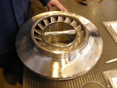
API 617 is not providing acceptance range and refers that to the manufacturer specification. The inspector shall review before and after dimensional inspection reports and check that aginst manufacturer acceptance criteria and make sure the change in dimension fall within acceptance range.
In the fourth step, the impeller is subjected to the dye penetration or magnetic particle test to make sure no crack developed during impeller overspeeding test.
Centrifugal Compressor Casing Inspection
The compressor casing “material test report (MTR)” shall be reviewed. The casing either is made by casting or forging. The material test report shall be verified aginst assigned ASTM material standard and make sure the chemical composition, mechanical properties e.g. tensile strength, yield strength, elongation and reduction of area are within acceptance range.
The heat treatment type, holding time and temperature also shall be verified. In some material type, the hardness value shall be measured by Brinell or Rockwell technique. You should make sure you can locate the hardness value in the MTR, and the value is less than maximum allowed value.
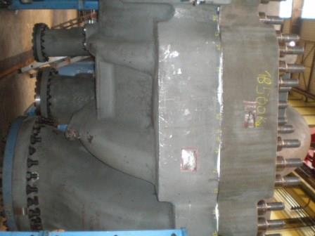
The API 617, contrary to the API 610 (for pumps) is not addressing the required visual inspection and the nondestructive testing amount in compressor casing. The amount of the testing depends on the agreement between compressor manufacturer and customer but addresses the test methods and acceptance criteria for NDE testing.
You should check approved inspection and test plan to see what NDE testing being considered for casing inspection and make sure you can locate those tests in the casing MTR.
API 617 requires the PT test be performed by test method addressed at ASTM E165, MT based on ASTM E709, UT based on ASTM A609 (casting) and ASTM A388 (forging) and RT based on ASTM E94.
The above mentioned ASTM standards are the test procedures, and you can not find acceptance criteria there. The API 617 requires the test interpretation be performed based on ASME Code Section VIII Div. 1 Appendix 7 (for Casting). This appendix covers all above tests e.g. PT, MT, RT, and UT.

If you refer to this appendix, you will notice this appendix in some tests refers you to some other ASTM standards. The most important ones are ASTM E446, ASTM E 186 and ASTM E280 for RT film interpretation.
These 3 standards have adjunct comparator radiographs that shall be used in film interpretation. The RT technician shall match the actual compressor RT films with these reference radiographs and decide about acceptability or unacceptability of the films.
You should review the NDE test report and make sure the NDE tests being interpreted and reported aginst correct assigned standard. As you might know, an indication might be a defect in one standard and be an acceptable imperfection based the other standard.
The acceptance criteria for welded components such as nozzles and attachments are referenced to ASME Section VIII Div.1 UW 51 and 52 for RT and Appendix 6 and 8 for PT and MT and appendix 12 for UT.
After successful completion of the Material Test Report Review (NDE reports included), you need to witness the hydrostatic testing.
Casing Hydrostatic Testing @ Centrifugal Compressor Testing
The compressor casing shall be subjected to the hydrostatic testing, similar to the other rotating equipment; the casing shall be tested at 1.5 times of maximum allowable working pressure.
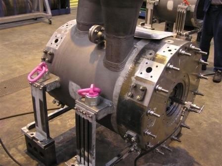
You as inspector or customer representative do not need to calculate the test pressure. The test pressure should be read from approved hydrostatic test procedure or approved compressor datasheet. The test result shall be considered satisfactory if no leak or seepage observed in 30 minutes (minimum time that compressor casing shall be under pressure).
The chloride content shall be less than 50 ppm if the casing material is the stainless steel. The pressure gage shall be calibrated, and you should verify calibration and expiration dates on the gage label and gage certificate.
The preferable pressure range gage is two times of the test pressure but in no case shall be less than 1.5 times and more than 4 times of the test pressure.
Gas Leakage Test @ Centrifugal Compressor Testing
The centrifugal compressor gas leakage test shall be performed after successful completion of the mechanical running test. The compressor shall be pressurized with inert gas to the maximum sealing pressure for 30 minutes. The test can be considered as the last test which is performed in centrifugal compressor testing.
The compressor end seals (contract seals) shall in the installed condition. The compressor shall be subjected to soap water bubble test. The bubble test can be done based on the requirement of the ASME Section V – Article 10 – Leak testing.
Household detergent shall not be used for soapy water solution. The specific leak test solution shall be purchased and used for the test. The test result would be satisfactory if no bubble development observed from joints, connections, etc.
Vibration Test & Analysis @ Centrifugal Compressor Testing
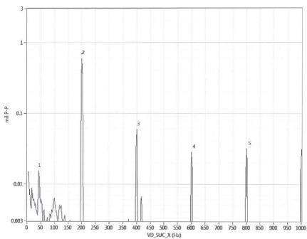
The API 617 only requires the centrifugal compressor vibration test and analysis being performed at shaft adjacent to the bearings during the aerodynamic performance test and in the mechanical running test. The proximitor probe is used for measurement and usually is handled by 4 probes, two for suction bearings X and Y axises and two for discharge bearing same X and Y axises.
You may also review the Third Party Inspection for Centrifugal Compressor article which can be considered a inspection instruction for centrifugal compressor testing and inspection.
You may also need a sample centrifugal compressor inspection and test plan.
The following content provides a sample general centrifugal compressor testing procedure which might be useful. The acceptance criteria have not been addressed in this test procedure. This is a very brief and general procedure.
Applicable Standards @ Centrifugal Compressor Testing
The applicable standards for centrifugal compressor testing are:
- API Standard 617; Centrifugal Compressor for Petroleum, Chemical and Gas Service Industries
- ASME PTC 10; Performance Test Code on Compressors and Exhausters
- BS EN ISO 5167-2; Measurement of fluid flow by means of pressure differential devices inserted in circular cross-section conduits running full – Part 2: Orifice plates
- BS ISO 5389 Turbo compressors Performance Test Code
Required Data for Centrifugal Compressor Mechanical Running Test
Following data need to be extracted for centrifugal compressor testing from design documents, datasheet and operating manual and to be available during the test.
Specified Operating Speeds
- Normal Operating Speed
- Minimum Operating Speed
- Maximum Continuous Speed
- Trip Speed
Maximum Shaft Vibration
- At Maximum Continuous Speed
- At Trip Speed
Lube Oil Data
- Oil Viscosity Class
- Oil Inlet Temperature
- Oil Inlet Pressure
- Maximum Oil Volume Flow Of Compressor
Shaft Seals
- Seal Type
- Seal Medium
Preparation for Centrifugal Compressor Mechanical Running Test
Typically a checklist is used to ensure all items are based on design and actual operating condition.
The following components are used from Centrifugal Compressor Testing Stand (Not Contract Items)
- Drive unit (Electric motor)
- Gear box
- Coupling (poss. with adapter)
- Intercooler
- Oil unit
- Process gas piping
- Instruments
- Vibration monitoring system
- Data acquisition equipment
The following components are used from centrifugal compressor (original)
- Coupling (poss. with adapter) X
- Seal gas panel
- Instruments
- Shaft vibration measurement equipment
Note: The coupling and instruments are used from both systems i.e. test stand and original components of compressor
Centrifugal Compressor Testing – Mechanical Running Test
The mechanical running test is done with the following sequence:
- The speed increase from standstill up to minimum driver control speed.
- Speed increase in steps of approx. 10% of maximum continuous speed up to maximum continuous speed (MCS) under consideration of the lateral natural frequencies.
- Continuations of operation until lube oil and bearing temperatures have stabilized.
- Speed increases up to trip speed. Test runs for 15 minutes at trip. Babbitt metal temperatures, oil inlet and outlet temperatures and pressures and the overall oil volume flow are measured and recorded once. Shaft vibrations are measured and recorded once at all contact measuring locations.
- Speed deceleration to MCS. Test runs for 4 hours at MCS. Babbitt metal temperatures, oil inlet and outlet temperatures and pressures and the overall oil volume flow are measured and recorded in intervals of about 20 minutes. Inlet and outlet temperatures and pressures of the handled fluid are measured and recorded. Shaft vibrations are measured and recorded at all existing measurement points in intervals of about 20 minutes. A vibration spectra analysis is carried out approximately in the middle of the 4 hours test run.
- Speed increase up to trip speed.
- Speed deceleration to final standstill.
Unfiltered and filtered displacement amplitudes and the corresponding phase angles will be recorded and plotted vs. speed during coast down. Bode plots during coast down.
After completion of the mechanical running test and after sufficient cooling-down the compressor will be checked according to the inspection and test plan.
Centrifugal Compressor Testing – Vibration Measurements & Analysis
Shaft vibrations and axial displacements are measured. Vibration measurements are carried out with the vendor measuring system. All other necessary instrumentation for vibration analysis needs to be available by centrifugal compressor vendors.
For assessment of the allowable amplitudes of the shaft vibrations according to design the monitoring systems installed in the test stand are used. For visualization and preparing plots a mobile diagnostic system are used.
Run out is determined and recorded. Only these values are binding for the machine. At low speed the shaft vibration monitor only indicates the slow-roll-signal.
If the measured slow-roll-signal values during the test run exceed distinctly the specified run out values, run out are controlled and, if necessary, refurbished after completion of the test run without repeating the test run.
Required Data for Thermodynamic Performance Test
Following data need to be extracted from a centrifugal compressor design book, datasheet and operating manual and to be available for calculations.
Operating Conditions
- Gas Type
- Mass Flow, Wet
Inlet conditions
- Pressure
- Temperature
- Relative Humidity
- Inlet Volume, Wet
Discharge Conditions
- Pressure
- Temperature
Performance
- Shaft power at compressor coupling (incl. losses)
- Compressor speed
- Polytropic head
- Polytropic efficiency
Similarly the centrifugal compressor testing medium and related operating parameter need to be identified. N2 normally is used as the test medium. Following also need be specified:
Test Meduim Inlet Condition
- Pressure
- Temperature
- Relative Humidity
- Gas Constant X Compressibility Factor
- Inlet Volume Flow, Dry
Test Meduim Discharge Condition
- Pressure
- Temperature
Performance
- Gas Power
- Compressor Speed
Centrifugal Compressor Testing – Thermodynamic Performance Test Procedure
Before starting the thermodynamic performance test the compressor is operated for a sufficient period of time at the calculated test conditions to demonstrate acceptable mechanical operation and stable values of all measurements.
All instruments are inspected separately and the measured variables in identical measuring planes are compared to each other.
The duration of the test is depending on the time needed to reach steady-state test conditions. This condition is insured by steady-state values of pressures and temperatures.
An automated data acquisition system is used. The data are recorded, processed and displayed online.
Centrifugal Compressor Testing – Measuring and Analysis
Previous to the test all measuring instruments for pressure and temperature are calibrated. On customer’s request the calibration can be redone after the test for one instrument each for pressure and temperature at the inlet and discharge port.
The inlet and discharge pressures and temperatures are measured on centrifugal compressor testing on the basis of the applicable documents.
The mass flow is measured according to BS EN ISO 5167-2
The shaft power will be calculated with the heat balance method.
For the mechanical power losses the design value is used.
The Reynolds Number correction is done in accordance to ICAAMC.
Measuring uncertainty per BS ISO 5389


